CRAZY TIME LIVE FRANCE
Vous êtes à la recherche des meilleurs jeux Crazy Time au Royaume-Uni ? Notre top 10 des casinos Crazy Time propose des jeux en direct, des bonus généreux et une chance de gagner gros.

Effectuer des dépôts et obtenir des bonus:
€2500
Kit de bienvenue
* + 225 FS,créer un compte, compléter votre profil,
Effectuer des dépôts et obtenir des bonus:
€500
Kit de bienvenue
* + 20 FS,créer un compte, compléter votre profil,
Effectuer des dépôts et obtenir des bonus:
€800
Kit de bienvenue
* + 300 FS,créer un compte, compléter votre profil,
Effectuer des dépôts et obtenir des bonus:
€500
Kit de bienvenue
* + 80 FS,créer un compte, compléter votre profil,
Effectuer des dépôts et obtenir des bonus:
€500
Kit de bienvenue
* + 100 FS,créer un compte, compléter votre profil,
Effectuer des dépôts et obtenir des bonus:
€500
Kit de bienvenue
* + 200 FS + Bonus Crab,créer un compte, compléter votre profil,

Effectuer des dépôts et obtenir des bonus:
€1000
Kit de bienvenue
* + 150 FS,créer un compte, compléter votre profil,
Effectuer des dépôts et obtenir des bonus:
€1000
Kit de bienvenue
* + 200 FS,créer un compte, compléter votre profil,
Effectuer des dépôts et obtenir des bonus:
€500
Kit de bienvenue
* + 200 FS,créer un compte, compléter votre profil,
Introduction au Crazy Time
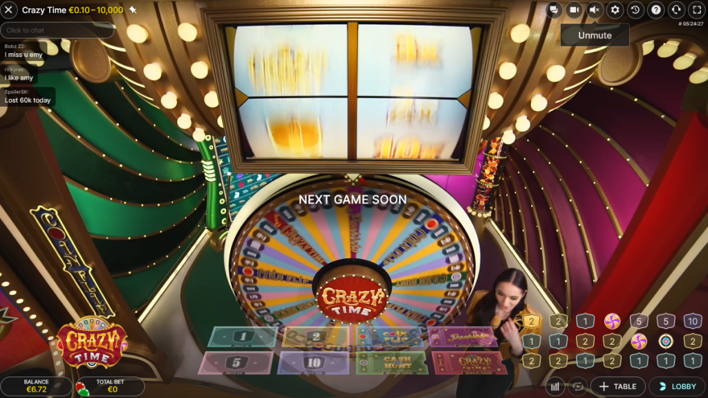
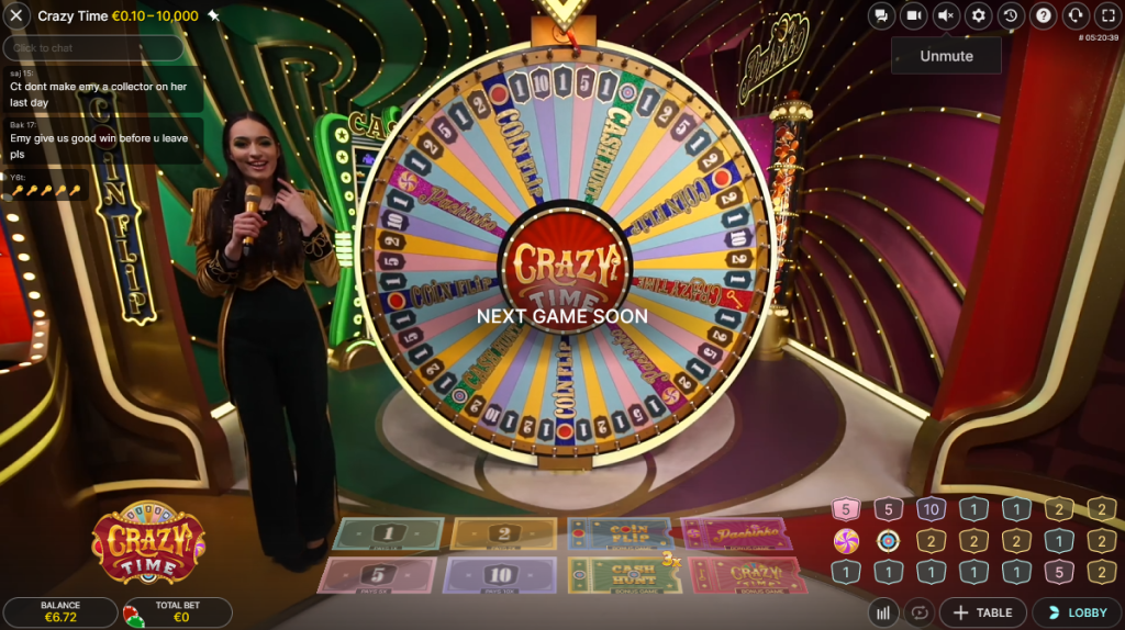
En tant que fervent amateur de jeux en ligne, je suis toujours à la recherche d’expériences nouvelles et excitantes. C’est ainsi que j’ai découvert Crazy Time, un jeu qui révolutionne le monde du casino en ligne. Crazy Time se présente comme une fusion étonnante entre une émission de télévision dynamique et un jeu de slot traditionnel. Ce qui rend ce jeu particulièrement captivant, c’est sa diffusion en direct. Imaginez-vous jouer en temps réel, guidé par des croupiers réels, ce qui ajoute une touche d’authenticité et de convivialité à l’expérience de jeu.
L’objectif de Crazy Time est à la fois simple et palpitant : il s’agit de prédire le résultat d’une grande roue tournante, divisée en plusieurs sections, chacune attribuée à une valeur de paiement différente. Cette roue, colorée et lumineuse, est au cœur du jeu et représente l’essence même de l’excitation chez les joueurs.
Pour ajouter à la complexité et au plaisir, Crazy Time offre une variété d’options de paris. Vous pouvez placer vos mises sur des numéros classiques, mais aussi sur des jeux bonus tels que le Coin Flip, le Cash Hunt, et le Pachinko. Chacun de ces paris a son propre ratio de paiement et des limites de paris, permettant ainsi aux joueurs de choisir leur stratégie selon leur appétit pour le risque.

Dès le début, le jeu nous plonge dans un univers où l’anticipation et l’excitation sont les maîtres mots. Avec chaque rotation de la roue, on ressent une montée d’adrénaline, en espérant que la chance soit de notre côté. C’est cette combinaison d’une présentation visuelle spectaculaire, d’une interaction en direct avec les croupiers, et d’une mécanique de jeu engageante qui fait de Crazy Time un incontournable pour les passionnés de jeux de casino en ligne.
Dans les prochains paragraphes, je vous guiderai à travers les détails des règles et du gameplay de Crazy Time, et vous partagerai mes conseils et stratégies pour maximiser votre expérience de jeu. Que vous soyez un joueur chevronné ou un débutant curieux, Crazy Time promet de vous offrir des moments de jeu inoubliables.
Les Manches Bonus de Crazy Time
L’un des aspects les plus exaltants de Crazy Time, et qui me tient personnellement en haleine, ce sont ses manches bonus. Il y a quatre étapes bonus, chacune offrant un mini-jeu distinct avec ses propres règles et caractéristiques uniques. Cela ajoute une couche supplémentaire d’excitation au jeu de base.
Premièrement, il y a le Coin Flip. Ce mini-jeu est exactement ce que son nom suggère : un lancer de pièce. Les côtés de la pièce sont de différentes couleurs, chacune avec des cotes différentes, et le jeu consiste à prédire sur quel côté la pièce atterrira. C’est un moment de pur suspense et d’excitation.
Ensuite, nous avons le Cash Hunt. Dans ce jeu, 108 multiplicateurs sont dissimulés derrière divers symboles. Le défi pour le joueur est de choisir le bon symbole, celui qui cache le multiplicateur le plus élevé. C’est une épreuve d’adresse et de chance, qui ajoute une dimension interactive très plaisante au jeu.
Le troisième mini-jeu est Pachinko. Ici, une série de multiplicateurs sont placés au bas d’un grand tableau, et un palet est lâché du haut. Le point où le palet atterrit détermine le gain du joueur. Il y a même un coefficient « double » qui peut potentiellement doubler vos gains. Chaque chute du palet est un spectacle en soi.
Enfin, le jeu bonus Crazy Time est le clou du spectacle. C’est un tour de roue supplémentaire, divisé en 64 segments, offrant des multiplicateurs encore plus élevés. En tant que joueur, vous choisissez une flèche parmi trois couleurs différentes, et le multiplicateur où s’arrête la flèche sélectionnée est le gain que vous recevez.
Jouer à Crazy Time en France
Passionné par les jeux en ligne, j’ai été ravi de constater que Crazy Time est facilement accessible aux joueurs français. Cependant, il est crucial de choisir le bon casino en ligne pour profiter pleinement de l’expérience. Pour cela, je m’assure toujours que le casino est fiable et sécurisé. Un casino de bonne réputation devrait être licencié, offrir des méthodes de paiement sûres et un service clientèle réactif.
Lorsque je recherche un casino en ligne pour jouer à Crazy Time en France, je prête une attention particulière à ceux qui offrent des bonus spéciaux pour ce jeu, ainsi qu’à la qualité de leur streaming en direct. Une bonne connexion et des croupiers professionnels sont essentiels pour une expérience immersive.
Je recommande également de vérifier les avis des autres joueurs et les forums de discussion pour s’assurer de la fiabilité du casino. Il est important de se rappeler que le jeu doit rester une source de divertissement et de plaisir. Ainsi, choisir le bon casino en ligne est une étape cruciale pour une expérience de jeu sécurisée et agréable.
Dans les sections suivantes, je partagerai avec vous d’autres aspects importants de Crazy Time, y compris comment maximiser vos chances de gagner et les meilleures stratégies à adopter. Restez à l’écoute pour plonger plus profondément dans l’univers passionnant de Crazy Time!
Stratégies et Astuces pour jouer à Crazy Time
En tant que joueur régulier de Crazy Time, j’ai découvert qu’il existe plusieurs stratégies qui peuvent augmenter vos chances de gagner. Bien sûr, il est essentiel de se rappeler que Crazy Time est un jeu de hasard, et aucune stratégie ne garantit une victoire à chaque fois. Cependant, une approche réfléchie et stratégique peut certainement améliorer votre expérience de jeu.
Une des stratégies les plus courantes est la gestion de votre bankroll. Il est crucial de fixer des limites pour vos mises et de ne pas les dépasser. Cela vous aidera à jouer de manière responsable et à éviter des pertes importantes. Personnellement, je définis toujours un budget de jeu avant de commencer et je m’y tiens strictement.
Une autre approche consiste à varier vos mises sur différents segments de la roue. Certains joueurs préfèrent miser sur les numéros avec des cotes plus basses, car ils apparaissent plus fréquemment, tandis que d’autres aiment le frisson de parier sur les jeux bonus qui offrent des gains plus élevés mais moins fréquents. J’aime utiliser une combinaison des deux, en répartissant mes mises pour couvrir à la fois des options sûres et risquées.
L’importance de jouer la version démo ne peut être sous-estimée. La version démo vous permet de vous familiariser avec le jeu sans risquer votre argent réel. C’est une occasion fantastique de tester différentes stratégies et de voir comment elles fonctionnent dans la pratique. Je passe souvent du temps à jouer en mode démo pour peaufiner mes tactiques et acquérir une meilleure compréhension du jeu.
Je conseille également de rester attentif aux statistiques du jeu. Crazy Time offre des statistiques détaillées sur les résultats des tours précédents. Bien que ces informations ne prédisent pas les résultats futurs, elles peuvent vous donner une idée des tendances et des fréquences des différents segments.
Enfin, il est important de jouer avec un état d’esprit positif et détendu. Le stress et la frustration peuvent conduire à des décisions impulsives. J’aborde toujours Crazy Time comme une forme de divertissement et non comme un moyen de gagner de l’argent. Cette approche me permet de profiter pleinement de l’expérience de jeu, quel que soit le résultat.
Dans la section suivante, je partagerai avec vous mes conseils sur comment choisir les meilleurs casinos en ligne pour jouer à Crazy Time en France, en mettant l’accent sur la sécurité, les bonus, et la qualité de l’expérience de jeu. Restez à l’écoute pour des informations précieuses qui vous aideront à naviguer dans le monde passionnant des casinos en ligne.
Jouer pour de l’Argent Réel vs. Démo Gratuite
Dans ma quête de divertissement au sein du monde des casinos en ligne, j’ai souvent été confronté au choix entre jouer pour de l’argent réel et utiliser la version démo gratuite de Crazy Time. Chacun de ces modes offre une expérience différente et répond à différents besoins.
Jouer pour de l’argent réel apporte indéniablement un niveau d’excitation supplémentaire. La possibilité de gagner (ou de perdre) de l’argent réel ajoute une dose d’adrénaline qui ne peut être reproduite dans aucun mode de jeu gratuit. C’est le choix idéal pour les joueurs qui recherchent le frisson du risque et le plaisir de la récompense potentielle. Personnellement, j’apprécie cette montée d’adrénaline, mais je suis toujours conscient des risques et je joue de manière responsable.
D’autre part, la version démo gratuite de Crazy Time est une excellente façon de se familiariser avec le jeu sans aucun risque financier. C’est une option idéale pour les débutants ou ceux qui veulent tester de nouvelles stratégies. Dans la démo, vous pouvez apprendre les règles, vous habituer à l’interface du jeu et comprendre les différentes manches bonus sans pression. Je recommande fortement de commencer par la version démo pour les nouveaux joueurs, car cela vous permet de construire une base solide avant de passer au jeu en argent réel.
L’Expérience Unique du Crazy Time
L’expérience de jouer à Crazy Time est véritablement unique et immersive. La combinaison d’un jeu dynamique, de croupiers en direct et d’effets visuels colorés crée une atmosphère qui ressemble plus à un jeu télévisé qu’à un jeu de casino traditionnel. Chaque session de jeu est une aventure en soi, avec des rebondissements imprévus et des moments de pure excitation.
J’ai eu le plaisir d’échanger avec plusieurs joueurs français qui ont partagé leurs histoires de succès avec Crazy Time. Ces témoignages varient des gains modestes mais satisfaisants aux gros jackpots qui ont changé leur expérience de jeu. Un joueur m’a raconté comment il a remporté une somme significative lors d’un tour de bonus Pachinko, tandis qu’un autre m’a décrit la jubilation de gagner plusieurs fois de suite sur les numéros à faible cote.
Ces histoires soulignent non seulement le potentiel de gains de Crazy Time, mais aussi l’aspect ludique et divertissant du jeu. Pour moi, Crazy Time est plus qu’un simple jeu de casino; c’est une forme de divertissement interactive qui allie chance, stratégie et spectacle. C’est cette expérience unique qui me pousse à revenir jouer, toujours avec enthousiasme et anticipation.
Conclusion et Recommandations Finales
En réfléchissant à mon parcours avec Crazy Time, je ne peux m’empêcher de souligner l’attrait unique de ce jeu en France. Crazy Time n’est pas seulement un jeu de casino en ligne ; c’est une expérience révolutionnaire qui fusionne l’excitation d’une émission de télévision en direct avec l’engagement interactif d’un jeu de hasard. Sa popularité croissante en France témoigne de son attrait universel et de sa capacité à offrir une expérience de jeu à la fois divertissante et potentiellement lucrative.
Pour les joueurs en France intéressés par Crazy Time, voici mes recommandations finales :
- Commencez par la Version Démo : Avant de vous lancer dans le jeu avec de l’argent réel, prenez le temps de vous familiariser avec Crazy Time en jouant à la version démo. Cela vous donnera une compréhension claire du jeu et de ses subtilités sans aucun risque financier.
- Choisissez le Bon Casino : Optez pour des casinos en ligne français réputés et fiables. Vérifiez leur licence, les options de paiement, les bonus offerts et la qualité de leur service client. Un bon casino devrait offrir une expérience de jeu sécurisée et équitable.
- Gérez votre Bankroll avec Prudence : Fixez-vous un budget de jeu et tenez-vous-y. La gestion responsable de votre bankroll est essentielle pour une expérience de jeu durable et agréable.
- Jouez Responsablement : Rappelez-vous que le jeu est une forme de divertissement et non un moyen de gagner de l’argent. Conservez une attitude positive et ne poursuivez pas les pertes.
- Profitez de l’Expérience : Crazy Time est conçu pour offrir divertissement et excitation. Profitez de l’aspect ludique et interactif du jeu, et voyez-le comme une opportunité de vivre des moments de détente et d’amusement.
En conclusion, Crazy Time est une aventure passionnante dans le monde des jeux en ligne, offrant une expérience inégalée qui allie chance, stratégie et divertissement. Pour les joueurs français, c’est une occasion unique de plonger dans un univers de jeu innovant et captivant. Que vous soyez un joueur chevronné ou un débutant, Crazy Time promet de vous offrir des moments mémorables et excitants. Bonne chance et surtout, amusez-vous bien !