CRAZY TIME LIVE NEDERLAND
Op zoek naar de beste Crazy Time actie in het Verenigd Koninkrijk? Onze top 10 Crazy Time Casino’s bieden live spanning, royale bonussen en een kans om groots te winnen.
Als een fervente liefhebber van online casino spellen, heb ik recentelijk mijn aandacht gericht op een bijzonder fascinerend spel: Crazy Time. Dit spel is een unieke mix van traditionele tv-show elementen gecombineerd met de opwinding van een klassiek slotspel. Wat Crazy Time echt onderscheidt, is de manier waarop het in real-time wordt gestreamd, compleet met live dealers die de ervaring levendig en interactief maken.
Hoe speel je Crazy Time?
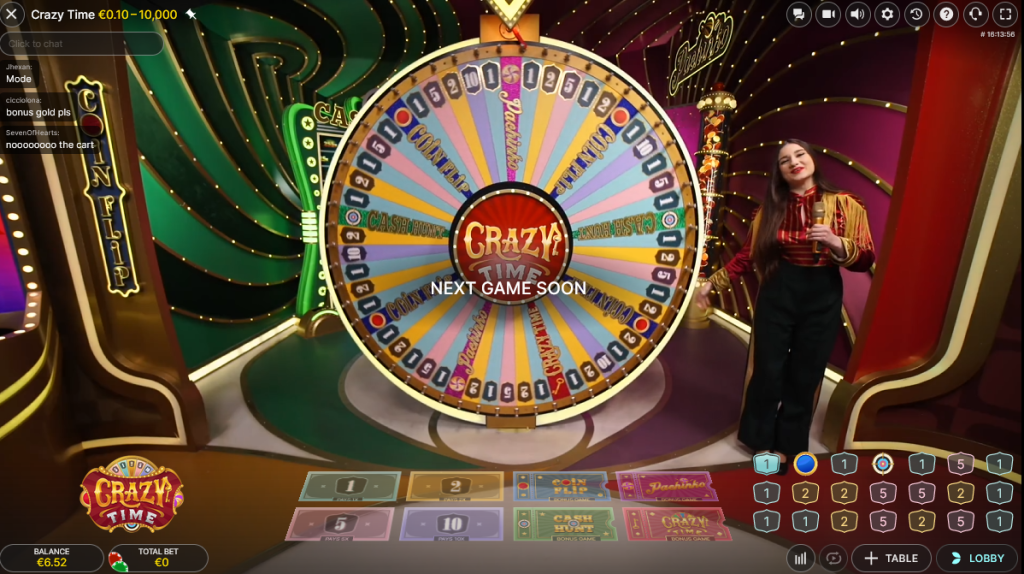
Om te beginnen met Crazy Time, is het allereerst belangrijk om de basis van het spel te begrijpen. Het centrale element van het spel is een groot, kleurrijk wiel dat in verschillende secties is verdeeld. Elke sectie vertegenwoordigt verschillende spelopties waarop spelers kunnen inzetten. Deze opties omvatten getallen zoals 1, 2, 5, en 10, maar ook speciale spelonderdelen zoals Coin Flip, Cash Hunt, en Pachinko.
Elke sectie op het wiel heeft zijn eigen uitbetalingsratio. Dit betekent dat de winst die je kunt behalen afhankelijk is van de sectie waarop je hebt ingezet. Het is essentieel om deze ratio’s te begrijpen, want ze beïnvloeden direct je strategie en potentiële winsten. Daarnaast is het ook belangrijk om te weten dat elke sectie zijn eigen inzetlimiet heeft, wat varieert afhankelijk van het casino waar je speelt.
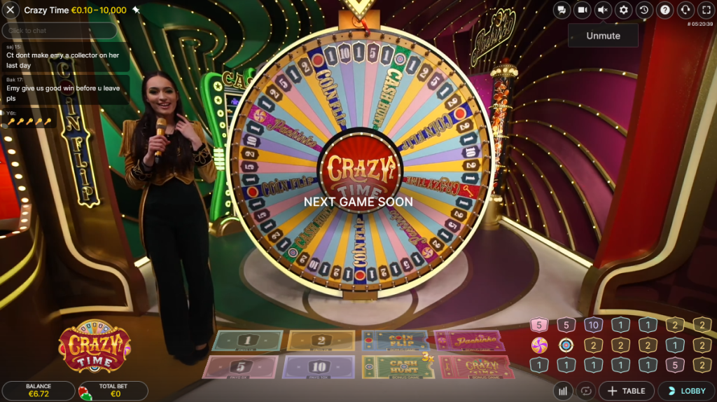
Het wiel van Crazy Time bestaat uit 54 sectoren. Naast de eerder genoemde getallen zijn er vier bonussecties. Deze bonussecties bieden spelers de kans op extra winsten en een verhoogd opwindingselement. Wanneer het wiel op een van deze bonussen landt, wordt een speciaal bonusspel geactiveerd waar nog grotere winsten behaald kunnen worden.
Crazy Time Bonus Rondes
Een van de meest opwindende aspecten van Crazy Time zijn de bonus rondes. Deze rondes voegen een extra laag toe aan het spel en bieden de kans op grotere winsten. Er zijn vier verschillende bonusstadia in Crazy Time, elk met unieke kenmerken.
- Coin Flip: Deze bonusronde is precies zoals het klinkt – een munt wordt opgegooid. De munt heeft twee zijden, rood en blauw, elk met een verschillende vermenigvuldiger. Voordat de munt wordt opgegooid, wordt willekeurig een vermenigvuldiger toegewezen aan elke kleur. Als de munt op de kleur landt waarop je hebt ingezet, wordt je winst vermenigvuldigd met de bijbehorende factor.
- Cash Hunt: Dit is een interactieve schietspelronde. Spelers worden gepresenteerd met een scherm vol met 108 verschillende vermenigvuldigers, die vervolgens worden bedekt door willekeurige symbolen. Spelers kiezen een doel en schieten erop, waarna de bedekte vermenigvuldiger wordt onthuld. De keuze is volledig aan de speler, wat een element van vaardigheid en strategie toevoegt aan het spel.
- Pachinko: In deze ronde wordt een fysieke puck gebruikt. Deze puck wordt bovenaan een groot bord met spijkers losgelaten. Terwijl de puck naar beneden valt, stuitert deze van spijker naar spijker, wat een element van pure kans introduceert. Aan de onderkant van het bord zijn verschillende vermenigvuldigers waar de puck in kan landen. Als de puck op een vermenigvuldiger valt, win je dat bedrag. Soms is er ook een ‘Dubbel’ veld, waarmee de vermenigvuldigers verdubbeld worden en de puck opnieuw wordt gelanceerd.
- Crazy Time Bonus Spel: Dit is de kroon op het spel en biedt de grootste winsten. Spelers worden meegenomen naar een ander wiel met 64 segmenten, inclusief vermenigvuldigers en dubbele waarden. Voordat het wiel draait, kiezen spelers een gekleurde pijl (blauw, groen of oranje). Waar de pijl stopt, bepaalt de winst. Dit kan leiden tot enorm hoge uitbetalingen, vooral als de pijl op een dubbele waarde of hoge vermenigvuldiger landt.
Hoofdspelronde van Crazy Time Evolution
In de hoofdspelronde draait alles om het draaien van het wiel. Spelers plaatsen hun inzetten op de verschillende secties van het wiel en de live dealer draait het vervolgens. Als het wiel stopt op een sectie waar je op hebt ingezet, ontvang je een uitbetaling gebaseerd op de uitbetalingsratio van die sectie. Het spannende aan dit basisspel is dat je nooit weet waar het wiel zal stoppen, wat elke draai onvoorspelbaar en opwindend maakt.
Bij het wedden op Crazy Time is het belangrijk om een strategie te hebben. Sommige spelers kiezen ervoor om kleine, regelmatige inzetten te plaatsen op de getallen om hun speeltijd te verlengen, terwijl anderen het risico nemen op de hogere uitbetalingen van de bonusrondes. Een populaire strategie is het spreiden van inzetten over meerdere secties van het wiel, wat de kansen om iets te winnen kan vergroten, hoewel dit natuurlijk geen garantie op succes is.
Crazy Time in Duitsland
De populariteit van Crazy Time heeft ook de Duitse markt bereikt, waar het snel een favoriet is geworden onder online casinospelers. In Duitsland is de toegang tot online casino’s goed gereguleerd, wat zorgt voor een veilige speelomgeving. Hier zijn enkele van de populairste casino’s waar Duitse spelers Crazy Time kunnen ervaren:
- 20bet: Bekend om zijn gebruiksvriendelijke interface en aantrekkelijke welkomstbonussen.
- Vave: Biedt een breed scala aan spellen naast Crazy Time, met sterke nadruk op klantenservice.
- Goldenbet: Staat bekend om zijn hoge uitbetalingspercentages en snelle uitbetalingsopties.
Als je in Duitsland woont en geïnteresseerd bent in het spelen van Crazy Time, is het registratieproces meestal eenvoudig en snel. Je moet basisinformatie verstrekken en soms een identiteitsbewijs om je account te verifiëren. Veel Duitse casino’s bieden ook speciale bonussen voor nieuwe spelers, zoals stortingsbonussen of gratis spins, die een geweldige manier kunnen zijn om te beginnen met spelen.
Crazy Time Online Casino Spel
Het spelen van Crazy Time online biedt verschillende voordelen. Ten eerste is er het gemak van toegang – je kunt spelen vanuit het comfort van je eigen huis, op elk moment. Ook bieden online versies van het spel vaak extra functies en statistieken die niet beschikbaar zijn in fysieke casino’s.
Bij het kiezen van een online casino om Crazy Time te spelen, is het belangrijk om de betrouwbaarheid en legitimiteit van het casino te overwegen. Zoek naar casino’s met een geldige licentie en positieve recensies van andere spelers. Het is ook belangrijk om de klantenservice, uitbetalingsopties en de beveiliging van financiële transacties te overwegen.
Veel online casino’s bieden tegenwoordig ook speciale Crazy Time apps. Deze apps bieden een meer gestroomlijnde en geoptimaliseerde spelervaring, vooral voor spelers die graag onderweg spelen. Voordelen van het gebruik van apps zijn onder andere snellere laadtijden, meldingen voor speciale aanbiedingen of bonussen, en soms zelfs extra functies die exclusief zijn voor mobiele gebruikers.
Crazy Time Demo voor Gratis Spelen
Voor degenen die nieuw zijn in het spel of voorzichtig willen zijn voordat ze echt geld inzetten, biedt Crazy Time een gratis demo-versie. Deze demo-modus is een uitstekende manier om het spel te begrijpen zonder financieel risico. Spelers kunnen het wiel, de verschillende inzetmogelijkheden en de bonus rondes verkennen zonder echt geld te gebruiken.
Het belang van het oefenen met de demo-versie kan niet genoeg benadrukt worden. Het stelt spelers in staat om verschillende strategieën uit te proberen, de regels te leren en een gevoel te krijgen voor het tempo van het spel. Dit is vooral nuttig bij een spel als Crazy Time, waar er verschillende inzetopties en bonusfuncties zijn om te begrijpen. Door eerst de demo te spelen, kunnen spelers een geïnformeerde beslissing nemen over hoe ze hun geld willen inzetten wanneer ze voor echt geld gaan spelen.
Crazy Time voor Echt Geld Spelen
Zodra spelers zich comfortabel voelen met het spel en klaar zijn om de spanning van het spelen met echt geld te ervaren, is het proces om te beginnen vrij eenvoudig. Het begint allemaal met het kiezen van een betrouwbaar online casino dat Crazy Time aanbiedt. Na het selecteren van een casino, volgt het registratieproces waarbij je je persoonlijke gegevens moet invullen en een account moet aanmaken.
De volgende stap is het storten van geld op je casino-account. De meeste online casino’s bieden diverse betaalmethoden, zoals creditcards, e-wallets en soms zelfs cryptocurrencies. Zodra je geld hebt gestort, kun je beginnen met het inzetten op Crazy Time.
Het opnemen van winsten is ook een eenvoudig proces, maar het is belangrijk om de opnamebeleid van het casino te kennen. Verschillende casino’s hanteren verschillende regels en tijdschema’s voor opnames. Sommige casino’s bieden instant opnames, terwijl anderen een paar dagen kunnen duren. Zorg ervoor dat je vertrouwd raakt met deze voorwaarden om teleurstellingen te voorkomen.
Afsluiting
Het spelen van Crazy Time biedt een opwindende en interactieve ervaring die uniek is in de wereld van online casino’s. Terwijl je geniet van de dynamiek en het plezier van dit spel, is het cruciaal om de juiste keuzes te maken, vooral als het gaat om het selecteren van een betrouwbaar casino. Een betrouwbaar casino garandeert niet alleen een veilige speelomgeving, maar zorgt ook voor eerlijke speelkansen en betrouwbare uitbetalingsprocessen.
Voor spelers in Duitsland is het belangrijk om te letten op casino’s die voldoen aan de lokale wet- en regelgeving. Zoek naar casino’s met een sterke reputatie, positieve beoordelingen van andere spelers en een geldige licentie. Let ook op de beschikbaarheid van klantenservice in het Duits, wat kan helpen bij eventuele vragen of problemen.
Hier zijn enkele laatste tips voor het spelen van Crazy Time:
- Begrijp het Spel: Besteed tijd aan het leren van de spelregels en oefen met de demo-versie voordat je echt geld inzet.
- Beheer je Bankroll: Stel een budget in voor je speelsessies en houd je eraan. Het is belangrijk om verantwoord te spelen.
- Spreid je Inzetten: Overweeg verschillende inzetstrategieën, zoals het spreiden van je inzetten over meerdere secties van het wiel.
- Geniet van de Ervaring: Vergeet niet dat spelen vooral leuk moet zijn. Wees voorbereid op zowel winsten als verliezen.
Door deze richtlijnen te volgen en te spelen bij gerenommeerde casino’s, kunnen spelers uit Duitsland en daarbuiten genieten van alles wat Crazy Time te bieden heeft, terwijl ze een veilige en plezierige speelervaring waarborgen. Veel geluk en veel plezier bij het draaien van het Crazy Time wiel!